| ERHS PHYSICS
Chapter 19.1 Notes: Diffraction |
||
| Diffraction is the bending of waves as it passes around the edges of barriers, such as when it passes through narrow slits. Look at this online explanation.
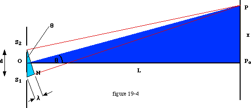
Light from most sources leaves the source at many different angles, and the waves of light will naturally overlap, or interfere at various locations away from such sources. Observing light as it passes through narrow slits would produce irregular diffraction results from such sources, since light striking the slit would be incident at several angles, and the waves of various frequencies would not be in step. Thomas Young arranged an apparatus that allowed monochromatic light to pass through a single narrow slit. Light that passes through this slit is all of the same wavelength, and in step, or coherent. This coherent light diffracts while passing through the slit and was allowed to fall incident upon two more narrow slits, which acted as reliable point sources of new circular waves as the light diffracted upon passing through them. Regular constructive and destructive interference was observed from this apparatus. On a screen in front of the slits, a single bright band occurs in the center and dark bands occur to the right and left of this central bright band. A repeating pattern of bright and dark bands occurs to the right and left. Bright bands are produced by constructive interference, and dark bands are where destructive interference occurs. With polychromatic light, the central band is produced by constructive interference of all wavelengths, and is therefore white. The side bands show up as spectra because the various wavelengths diffract at different angles and spread out. Study the diagram in figure 19-4 below. This is similar to the appratus Young used, and can be used to accurately determine the wavelength of monochromatic light. Using a diffraction grating whose distance d between slits is known, one can place a screen at a known distance L from the grating, and the distance x from the central band (Po )to the first order bright band at point P can be measured. The central band cannot be used in the calculation since it is independent of the wavelength.
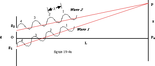
The first order bright band appears where it does ( at point P), because that is the next location, left or right of the central band, where constructive interference will occur. This location must be where two wave crests, one from each slit, interfere constructively. Even though the distance d between slits is NOT related to the wavelength, crests of two waves of identical length have to arrive at P simultaneously to produce a bright band there. Notice in the diagram that line wave path S1-P is longer that path S2-P. That means that the light wave has to travel farther from slit one. Imagine a series of wave crests emanating from slit one and slit two as shown in figure 19-4a below.
The two waves left the slits at the same time, and the one that left slit 1 has farther to go, but yet two crests both arrive at the first order bright band at point P simultaneously. The first crest from wave 2 reaches point P before, and therefore cannot be interfering with the first crest from wave 1. But what if the second crest from wave 2 arrives at the same time as the first from wave 1? This could occur if line S1-P is exactly 1 wavelength longer than S2-P. At the first order bright band, closest to the central bright band, the difference in path lengths is only one wavelength. So, if we can determine the difference in lengths of the two paths from the slits to the first order bright band, we can determine the wavelength. In the diagram, line O-P bisects angle Po-P-O. Line S1-N is constructed such that sides S1-P and N-P are equal in length. path S1-P is therefore longer than path S2-P by the length S1-N, which must be one wavlength (lambda.) To determine the length of S1-N therefore yields the wavelength of the light used in the experiment. Consider the geometry of figure 19-4 carefully. At first it appears that angle S1-N-S2 is a right angle, and therefore similar to angle O-Po-P. This is not the case however. Figure 19-4 cannot be drawn to scale as L is about 10,000 times longer than d. Lines S1P and S2P in actuality are nearly parallel, and angle S2-S1-N is very close to a right angle and is similar to angle O-Po-P. This makes side S1-N,(d), similar to side P-Po (x) , and line S1-S2 similar to side O-P (L). Because the two triangles S1-N-S2 and O-Po-P are similar, the ratio of any two sides on one triangle is equal to the ratio of the two similar sides on the other. The ratio of x/L is equal to the ratio of lambda /d: lambda / d = x / L and lambda = xd / L ************************************** Homework: assign. #1: chapter 19, questions 1-5 AND problems 16-20 Lab: measuring wavelength, page 446 in text. |
||

