| ERHS PHYSICS
Chapter 18.2 Notes: LIGHT |
||||||||||||||||||||||||||||||||||||||||||||||||||||||||||||||||
Notes: Chapter 18.2
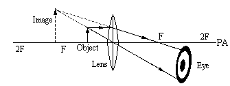
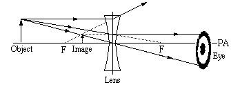
LensesTypes of lenses Convex lenses Converging lenses follow these three rules of refraction: Concave lenses Diverging lenses follow these three rules of refraction: Definitions and ConceptsLenses have curved surfaces, or a very large number of flat surfaces located at slightly different angles. (i.e., Fresnel lens) Converging lenses (positive lenses) are thicker at the center than at the edges. Diverging lenses (negative lenses) are thicker at the edges than at the center. (Only thin, single lenses are dealt with in this course. Note as well that the terms concave and convex, as applied to lenses, can be misleading. A meniscus lens has both a concave and a convex surface, but the thickness at the centre compared with the edges determines if it behaves as a converging or a diverging lens.) The optical center of the lens is located at its geometric centre. The principal axis is a construction line drawn perpendicular to the lens, through the optical centre. Rays parallel to the principal axis will converge when passing through a converging lens, and diverge when passing through a diverging lens. The principal focus (F) is a point on the principal axis where light comes to a focus (for a converging lens) or appears to be diverging from (for a diverging lens). Two foci exist, equidistant on either side of the lens, since light behaves the same way when travelling in either direction (Principle of Reversibility). The two foci, F and F' are called the primary principal focus and the secondary principal focus, respectively. F, sometimes also referred to as the primary focal point, is shown on the right side of a converging lens, and on the left side of a diverging lens, while F', the secondary focal point is shown on the opposite side of each respective lens.) Ray diagrams are used to show rays passing through a lens. Ray diagrams can be useful in determining the characteristics of an image formed by a lens. By convention, incident rays are shown travelling from left to right on ray diagrams. A dotted line is usually drawn through the lens at the optical center, perpendicular to the principal axis. Ray diagrams should always be drawn and labelled neatly, accurately, and to some appropriate scale. The focal length is the distance between the principal focus and the optical centre of the lens. The focal plane is an imaginary plane perpendicular to the principal axis at the focal point. Parallel rays will converge through a converging lens somewhere on the focal plane. Incident light rays are refracted twice by a lens; once at each boundary. Partial reflection may also occur. (In optical systems, partial reflection is undesirable. It can be minimized by using optical lens coatings. Coated lenses provide superior image quality.) To simplify matters on ray diagrams, incident rays can be shown to refract at the construction line passing through the optical centre of the lens. For a thin lens this leads to a reasonably close approximation because the lateral displacement is quite small. Light rays that have travelled over a large distance are effectively parallel. Lenses can form either real or virtual images. The rules for drawing ray diagrams for converging and diverging lenses can be used to determine the characteristics of an image formed by a lens. Lens equations can be used to determine the characteristics of an image. Refer to page 381 for lens equations. A diverging lens always forms an erect, virtual image which is diminished in size. It is located closer to the lens than the object, between the principal focal point and the lens. To correct for spherical aberration in lenses, achromatic lenses can be used. (Spherical aberration in lenses can be corrected by using aspheric lenses, or by using thin lens combinations which cancel out aberrations. Achromatic lenses, designed to correct for chromatic aberration at some wavelengths, can also help to reduce spherical aberration.) Lens defects are called aberrations. They hinder the quality of the image formed in an optical system. Lenses are used in many different kinds of practical applications. (Several should be studied.) An optical system may use a combination of mirrors, lenses, prisms, and other kinds of optical devices. An image formed by one component in an optical system can serve as an object for a different component. The image characteristics formed by converging lenses depend on the location of the object. This table summarizes the characteristics of images found in a converging mirror based onthe location of the object. Image Characteristics
Rules for Drawing Ray Diagrams for Converging and Diverging Lenses(Parenthetical remarks refer specifically to diverging lenses)
Interactive simulation of ray diagrams Homework: Set#3: chapter 18, questions 10-12, problems 35-39 Activities: use the Ray Box and Optics kit to study the properties of both converging and diverging lenses. |
||||||||||||||||||||||||||||||||||||||||||||||||||||||||||||||||


